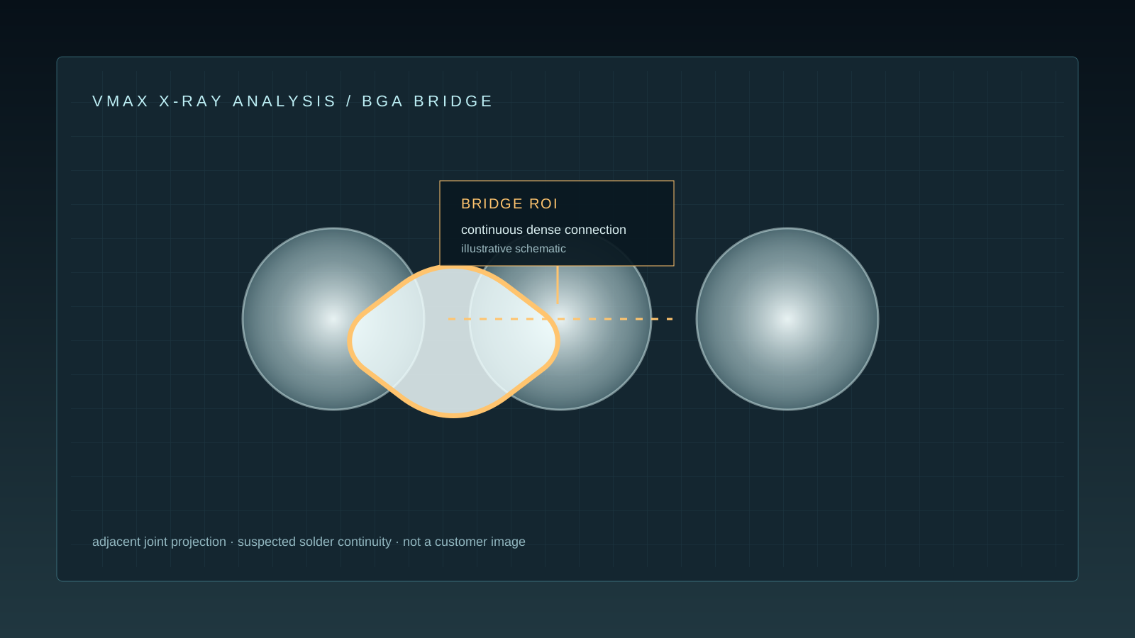
BGA bridge inspection uses X-ray image evidence to review adjacent solder joints that are hidden by the package body during optical inspection and supports solder joint analysis.
Reviewing adjacent BGA joints
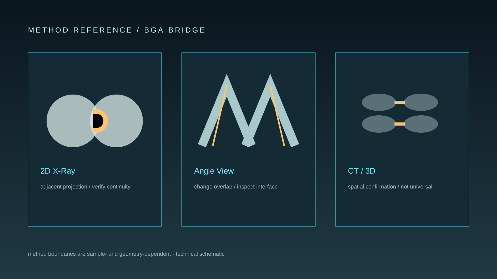
Industrial X-ray inspection can support review of solder continuity, joint boundaries, and projection overlap between neighboring BGA balls.
- Compare joint spacing across a controlled view
- Use angle or CT review when projection overlap limits interpretation
Inspection target
Adjacent BGA solder joints, pads, and package-side structures where projected solder continuity or inter-joint separation needs review.
Inspection considerations
- Compare neighboring joints under a controlled orientation and record the image direction.
- Separate a possible solder bridge from projection overlap, joint offset, or gray-level variation.
Measurable observations
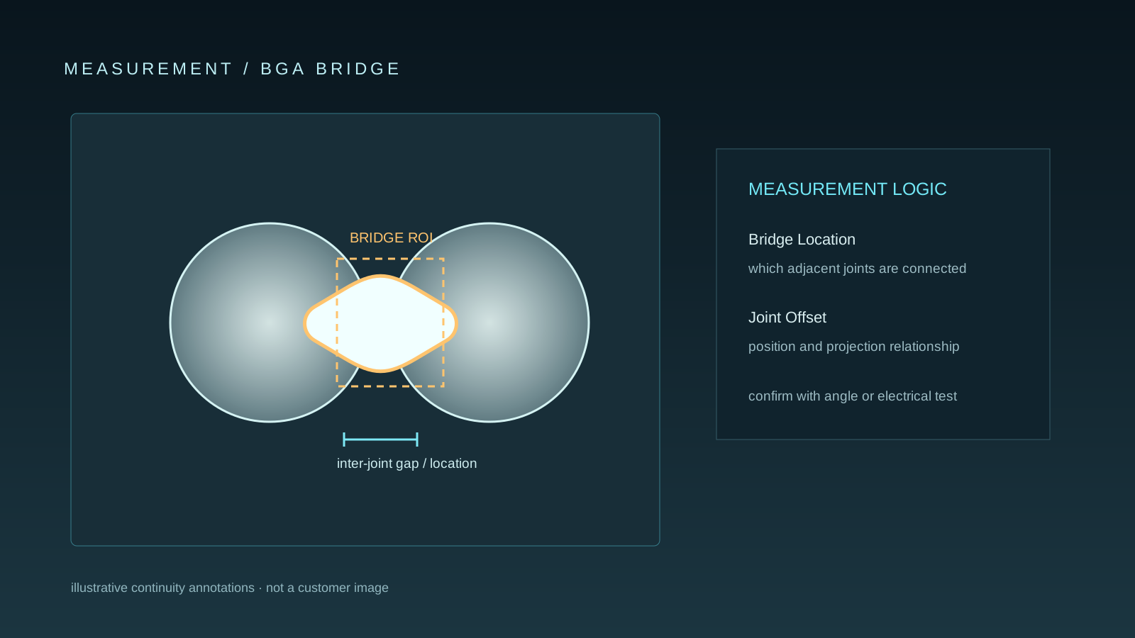
- Bridge location: Record row, column, neighboring joint IDs, and the suspected connection area.
- Inter-joint gap: Measure projected separation using a defined image scale and view.
- Joint offset: Review solder position relative to the pad center and adjacent joint.
Process and troubleshooting guidance
- Align suspected bridge locations with stencil, placement, SPI, and reflow records.
- Use a different view or higher-resolution review when projection overlap limits interpretation.
Capability boundary
- A single 2D projection can combine structures at different depths.
- X-ray findings identify image evidence for engineering review; final disposition should use applicable product criteria and verification data.