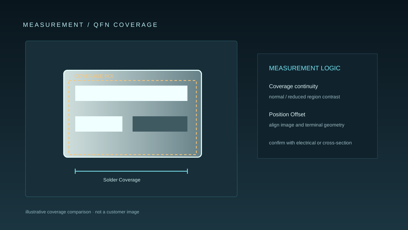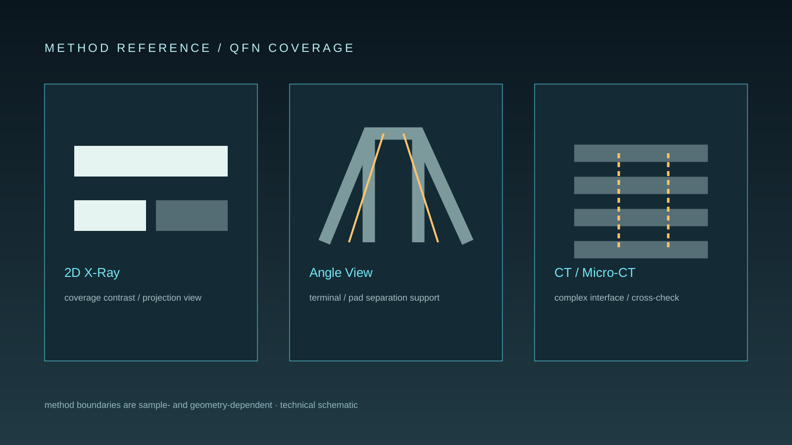
Industrial X-ray inspection helps engineers review hidden QFN solder coverage when the center pad and surrounding joints cannot be assessed optically, supporting solder joint analysis.
Evaluating hidden solder coverage
A repeatable X-ray inspection setup can help compare solder coverage, joint continuity, and structural variation across QFN samples.
- Keep sample orientation and imaging conditions comparable
- Relate image observations to pad design and process records
Inspection target
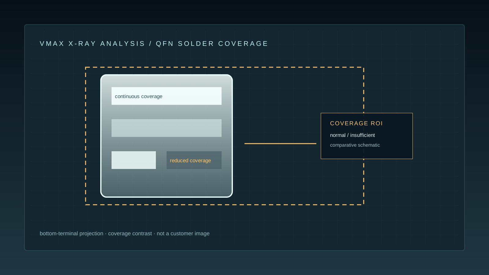
The hidden QFN center pad and perimeter solder joints where coverage and continuity cannot be fully assessed from the component surface.
Inspection considerations
- Use the same sample orientation, exposure setup, and image scale when comparing solder coverage.
- Separate insufficient solder indications from pad geometry, package offset, and projection effects.
Measurable observations
- Solder coverage: Record apparent coverage within the center-pad or joint ROI.
- Joint continuity: Review continuity and boundary evidence across the solder region.
- Variation by location: Compare center, perimeter, and corner areas across a controlled sample set.
Process and troubleshooting guidance
- Relate image findings to pad design, paste volume, placement, reflow, and process records.
- Retain image conditions and ROI definitions so repeated inspections remain comparable.
Capability boundary
- X-ray provides non-destructive evidence of hidden solder coverage but does not by itself establish a universal acceptance limit.
- Final assessment should use the applicable drawing, customer specification, and supporting process evidence.